Oct 10, 2016
Building a Voice Controlled Home Automation Model — Part 2— The Circuit
This is the second part in the Building a Voice Controlled Home Automation series. You can find the first part here.
Here’s a reminder of some of the stuff you might wanna read up on to get the best value from this tutorial:
- You have to have a basic understanding of circuits; how to light up an LED with a resistor and some batteries.
- You need to know the different parts of a bread board and how to hook one up.
- You might also want to know how to solder circuit components on PCBs. I had a friend help with this, he’s more experienced in the field; so taking my circuit diagram (and breadboard prototype) and turning it into a very compact PCB circuit was a piece of cake.
- To build the Android application that does voice control, you need to have a good understand of Java (or some OOP language) and the Android SDK.
- Also, you need some form of experience with writing basic programs for the Arduino.
For this part, numbers 1, 2, 3 & 5 are quite important.
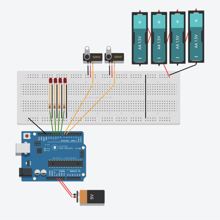
Today, we’re gonna take a look at the circuit diagram really closely and dissect the components so we can get a better understanding of how the whole thing comes together.
High Level Overview
I will go over the parts of this circuit but it’s still important to check out some of the links above to get a better, broader understanding of the components and how they work, especially if you’re new to electronics.

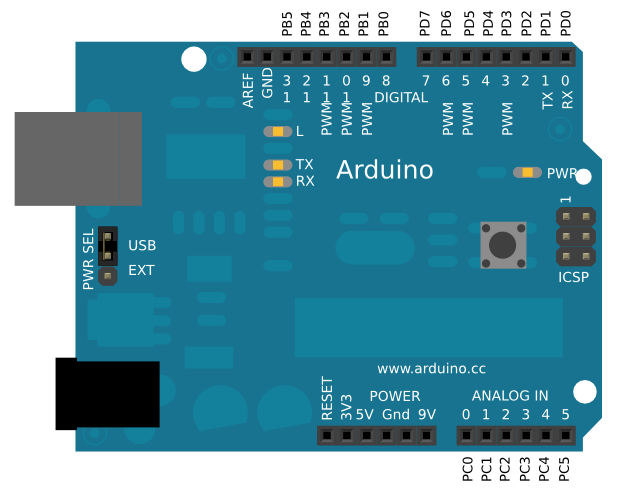
1. Arduino

This is where all the “logic” happens. The other components depend on this to receive signals that tell them what to do. It has numbered output ports running along each side. So if, for example, you connect an LED to 11, and you want to turn it on, you simply write code to send a HIGH signal to 11 like so:
digitalWrite(11, HIGH);
The entire functionality of an Arduino happens in two functions, namely: void setup() and void loop().
setup() is where you write code that you want to happen only once, after each power up or reset of the Arduino board.
loop() keeps getting called repeatedly for as long as the board is on and functional. It is in this function that all the magic happens. In this function, you can keep checking if there’s a new message from our Android application and then turn on/off the appropriate LED.
2. Bread Board
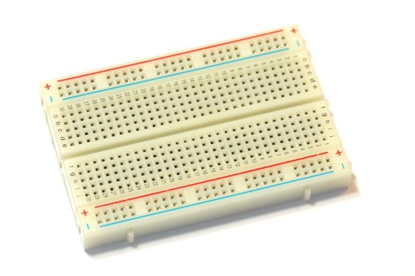
This is a prototyping tool that lets you get your circuit up and running relatively fast with a bunch of jumper wires and components.

The holes on the horizontal lines on either side are all connected, while the holes on the vertical lines in the middle row are connected. In some breadboards, all the holes in the middle row have coordinates (in the form of letters and numbers) printed on them. An example coordinate is j15. Unfortunately, these coordinates my differ because of the size of the breadboard or they might not even be printed at all.
3. LEDs
These light up when you connect them to a power supply, simple. Sometimes LEDs need a higher voltage to light up and one solution is to use a resistor to bump the voltage up.
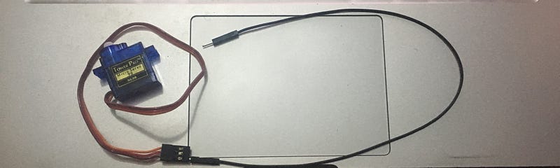
3. Servos
A servo is a kind of motor that has a shaft which can be positioned to specific positions by sending it a special signal. The shaft can remain in this position as long as the signal remains on the input line.
The servos has three wires connected to it: negative terminal, positive terminal, and the input line. It is this input line that will be connected to an Arduino output port.

Notes on power supply
- There are two power supply sources because we need to power the Arduino AND the components of the circuit. The 9V battery in the diagram is only connected to the Arduino and it serves as it’s power source.
- I didn’t use a 9V battery in my setup, I just plugged in the Arduino using a USB cable. During development; it was plugged into my MacBook and in “production”; I plugged into a wall outlet using a USB power adapter.
Prototyping the circuit
Below is a picture of my own (old, dirty) breadboard. It’s coordinates are what I’ll use to describe where stuff should be connected to.
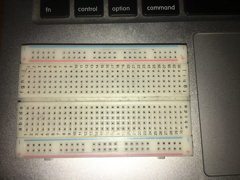
Note: This isn’t about memorizing the coordinates I specify. The best option would be to actually understand how the breadboard works by reading my explanation above AND the link at the beginning of the post.
- Snap your AA batteries into your battery holder and connect the negative terminal to one of the negative holes in the top row of the breadboard. Do the obvious thing for the positive terminal too.
- Take a jumper cable and use it to connect any hole from the upper negative row to any hole in the lower negative row.
- Connect the negative legs (the shorter ones) of all four LEDs in a straight row;
j8,j10,j12andj14. - Use your jumper cables to connect the corresponding “i” hole to the lower negative row of the breadboard. This means that you should connect the
i8,i10,i12andi14to the lower negative row. - Now, we take our positive LED legs (the longer ones) and connect them to the odd “j” rows;
j7,j9,j11andj13. - Take 4 100 ohm resistors, connect one leg of each to the corresponding odd “i” rows (
i7,i9,i11andi13). Take all the other legs and connect them to the Arduino’s output pins. Any ones would do, but I used 8, 9, 10 and 11. Feel free to use wires to extend the length of the leg(s) as you wish. - Connect any hole in the lower negative row to the GND (ground) port of the Arduino. By doing this, everything connected to ANY negative row on the bread board will be connected to the ground port of the Arduino.
- For the servos, we connect the negative terminal to the any negative hole on the breadboard and again, do the obvious thing for the positive terminal. Your servo might have all three wires joined together with a female header, you can use a male to male jumper cable to separate them as in the image below.
9. Finally, connect the input lines of the servos to the Arduino. I used port 6 and 7 for mine.
If you’ve managed to follow those instructions correctly, you should have something very similar to the circuit diagram.
To test this, you can load the code in this Gist I created, unto your Arduino (using the Arduino IDE) and run it. The servos will alternate angles a couple of times and the lights shall flash on and off — if you got everything right that is.
In your code, make sure to change the variables if you used different outputs on your Arduino to the right one.
If you don’t get it right…do not despair. It’s quite a lot to get right once, if you’re new to this kind of thing. It might take many frustrated retries and a lot of Googling.
It’s also useful to read the code in the Gist over and over again till you understand what’s going on.
When you’re certain that the circuit works as it should, it would be a good point to solder all the components on a PCB, if you can. A PCB would be compact and you won’t have to worry about components getting removed like you would with a breadboard.
What’s next
- In the third article, we shall write more code for the Arduino to make it listen for instructions and perform the right actions, like opening the doors and turning on the lights.
- In the fourth article, we’ll build the Android application with Wit and Pubnub’s APIs.